A while back one of our printer forum members submitted the article “Canon i960 Printer Cover & Base Removal”. Another one of our community members, wfmcg, replied that he had created a Canon i960 teardown document with pics. I asked if he’d be willing to send it to me, and did. I was impressed and asked permission to post, so here it is:
Canon i960 Waste Ink Tank Pad Replacement
Important!: First Please read this note at the bottom of the pagebefore starting.
To start the tear down, observe unit for any tab release holes.
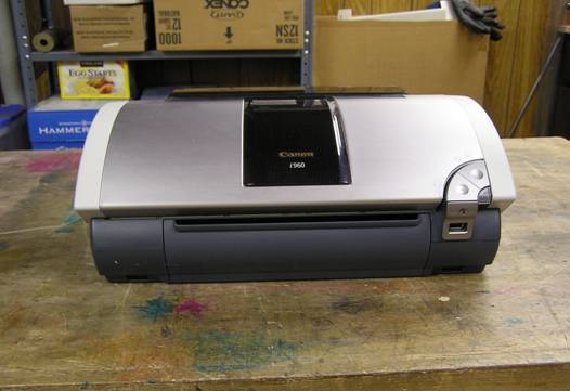
Figure 1
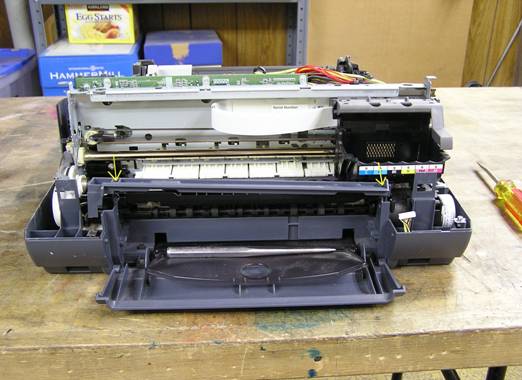
In this demonstration, notice that I have removed the print head.This was because the pigmented black had become badly clogged.While I was soaking it in a shallow bath of 50% Clear Ammonia and 50% Distilled Water for a couple of days, I decided to clean out the wastetank absorbent pads.While I went through the shut down procedure, which parked the print head carrier,It would be easier to unplug the printer while the carrier is still in the middle, at the“change ink cartridge” position. That way you will have more room to remove thesquare “stone” below the print head for cleaning.You can see the square stone with the ink still in it in figure 22,while in figure 20 you can see it after it’s been cleaned.(I had to re-take figure 20 for clarity.)
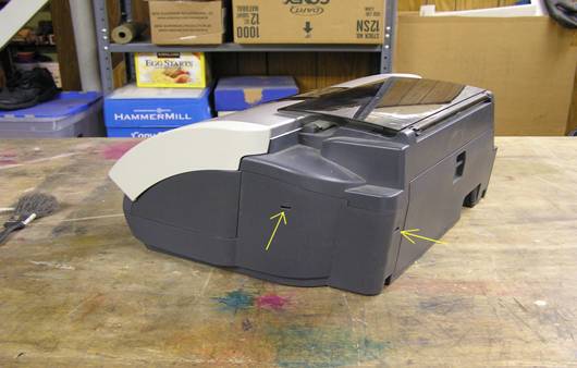
Figure 2
Notice the two release slots. One on right side and one on right rear.Use thin screwdriver to push in locking fingers.
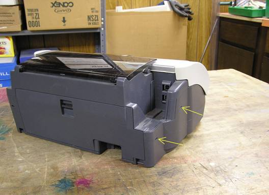
Figure 3
Two release slots on left side, front and rear.
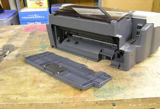
Figure 4
While we’re back here remove paper jam door.
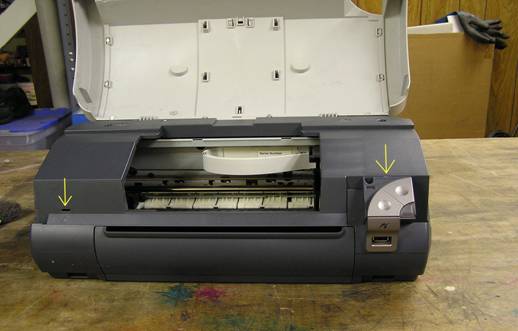
Figure 5
Two more release slots. One on the left front and one behind the start button console.

Figure 6
Remove the two screws from the start button console.
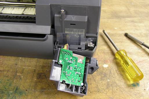
Figure 7
I like to replace the screws into their sockets so they don’t get lost.
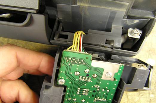
Figure 8
Next, gently remove the multi-wire connector.
Figure 9
After releasing all the locking fingers, gently remove the top.
Now push on the small locking fingers in the top of the spreader bar and remove.
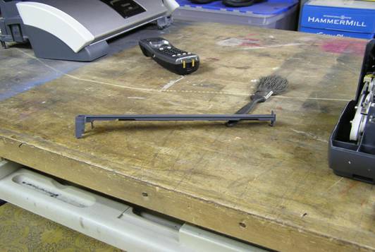
Figure 10
Set the spreader aside in a safe place. 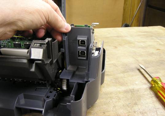
Figure 11
Remove the now loose USB cover plate. 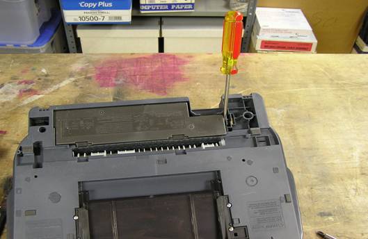
Figure 12
Flip unit over, being extremely careful not to damage the mylar location disc and location strip.Use flat screwdriver to release power supply locking clip.
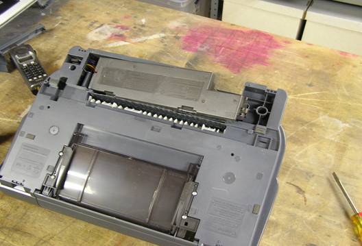
Figure 13
Pop up right side and pull to the right.
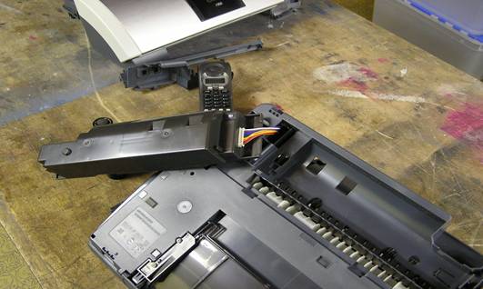
Figure 14
Flip power supply over and gently unplug multi-wire connector.
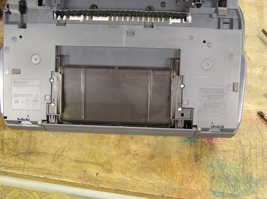
Figure 15
If desired, the lower paper tray may be removed with these four screws.
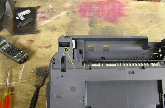
Figure 16
Find the diagnostic connector in a well at the rear of the bottom of the base.
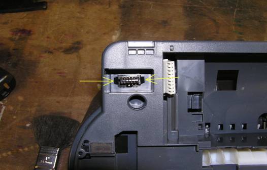
Figure 17
Use a small screwdriver to push in on the clips and push through hole in base.
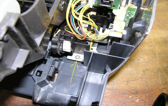
Figure 18
Remove left rear interior mount screw
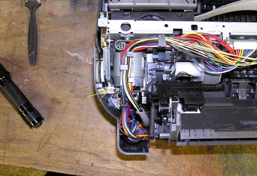
Figure 19
Remove right rear interior mount screw
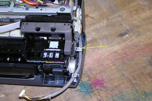
Figure 20
Remove right front mount screwLeave clip attached to base for now.

Figure 21
I like to leave myself notes as to the location and sizes or lengths of the screws I have removed. Notice the yellow letters. s=short, l=long, sm=short machine thread.
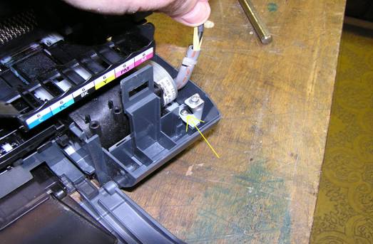
Figure 22
Later when removing clip from base, note screw location.
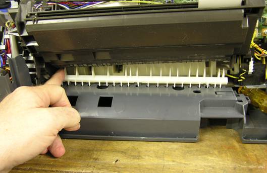
Figure 23
As you lift out printer carriage assembly from the base, the paper guiding fingerswant to fall out. Note the direction of the fingers and how they are clippedon to the base, so you can reinstall them properly.
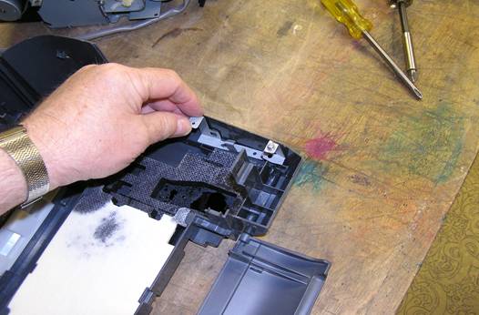
Figure 24
Remove mounting clip from base by removing screw shown earlier andput in a safe place.
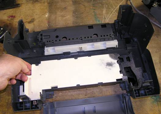
Figure 25
We have now arrived at the waste ink (tank) absorbent pads.Notice the pads directly below the print head parked position are the most saturated.
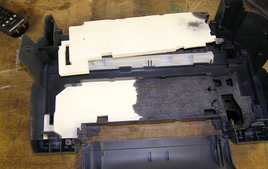
Figure 26
With the top pad removed you can see the amount of ink the lower pad has accumulated.
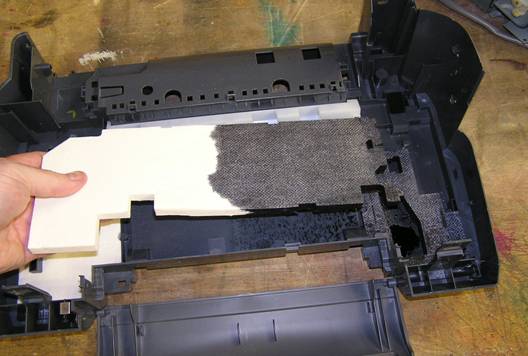
Figure 27
Remove the pads for replacement or cleaning.

Figure 28
There are two pads below where the print head parks.Notice the different texture on one side of the pads.The cloth-like side of the pads goes down on the bottom pad,and up on the top pad.
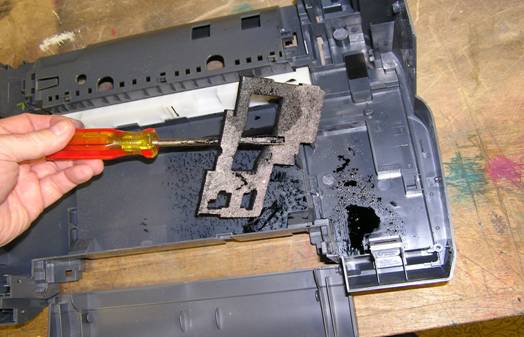
Figure 29
Again, remove the pads for replacement or cleaning.Seeing as this printer has been discontinued by Canon, cleaning is probably youronly option. When cleaning the pads, it becomes necessary to squeeze out the water at some point.This squeezing causes the pads to compress to about half their thickness. So when you reinstall them they do not fill to the same height as before. I have found this not to be a problem. As they fill up with ink again, they expand as they suck up the ink, albeit not completely to their pre-washed thickness.It has been suggested not to squeeze out the pads, but to just let them drip dry fora few days. Although I have not tried this yet, it might be the better option.
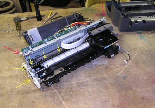
Figure 30
Important !!! A note of caution here !!!When handling the printer carriage, be very careful of the Mylar location disc on the left of the carriage and the Mylar location strip (Yellow Arrows) running along the back of the print head carriage.Please DO NOT DAMAGE THESE. When lifting printer carriage out of base, use the tabs (Red Arrows) to do the lifting. As Usual reassemble in reverse order.